Wondering how to check if your golf cart controller is working properly? Testing it can seem tricky, but with the right steps, you can identify issues quickly. Knowing what to look for helps you troubleshoot before costly repairs or replacements.
In this article, you’ll learn simple, safe methods to test your controller’s voltage and signals. This way, you can diagnose whether it needs fixing.
Keep reading for clear instructions and tips to get your golf cart back in top shape.
Gather Your Safety Gear and Tools First
First, gather your safety gear and tools before touching any wires. You’ll need safety glasses and insulated gloves to guard against sparks and electrostatic shocks. Protective clothing is essential to prevent contact with battery residue and grime, while closed-toe shoes protect your feet. For tools, a digital multimeter with DC voltage capability is your primary diagnostic device. A repair manual helps you identify terminals and test points accurately. Start your inspection procedures now—use a flashlight to identify corrosion or burnt insulation around the controller area. Clean cloths are useful for checking loose connections. Secure the equipment by placing wheel chocks around the cart and setting the parking brake. Disconnect the battery charger cords to eliminate power sources. Gathering everything beforehand ensures a smooth, interruption-free testing process. This preparation keeps you safe and ensures your diagnostics are accurate. For context on controller performance benchmarks, refer to reviews that compare top picks on quality. Knowing the expected voltage output also helps when matching your controller to a high-quality lithium battery that delivers consistent power. For additional guidance, consult top covers for golf carts to protect your equipment from weather damage.

WET-WEATHER GRIP. Water absorbet Sure-Grip Autosuede knit palm provides improved fit and sure grip in rainy conditions, conforming to your hand and club for unmatched control.

Essential for Golf Cart: this golf glove is designed for golf push cart handles; Made with 600D Oxford cloth on the outside and a fleece lining, its universal size provides windproof warmth and keeps hands dry and comfortable during cold weather; It's ideal for morning tee shots or golf
Step 1: Check Battery-Pack Voltage Before Opening Anything
To check the battery pack voltage before opening any components, start by powering down the cart completely. Turn the key to the off position and disconnect the charger. If your cart has a tow or maintenance mode switch, set it accordingly. Block the wheels to prevent movement, then open the battery compartment just enough to access the main terminals. Using a multimeter set to DC volts, place the red probe on the main positive terminal and the black probe on the main negative terminal. Read the total pack voltage; there’s no need to test individual batteries at this stage. Once the pack is verified, ensure your windshield is also DOT-approved for safe road use.
Compare this reading to your cart’s nominal voltage—36V, 48V, or 72V. A fully charged lead-acid pack can often read slightly higher than its nominal voltage. Pay attention to the overall battery awareness: a low reading indicates weak batteries or loose connections, not necessarily a problem with the controller. Follow safe charging practices for 8-volt batteries to ensure the pack is properly conditioned before testing. To verify voltage consistency and remove surface charge effects, let the pack rest for at least six hours before rechecking. If the pack voltage is significantly lower than normal, address that issue before proceeding with any further inspections.
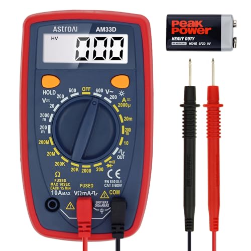
Additional Tips - The following incorrect operations may cause the multimeter not to show results: Firstly, the plugs of test leads are not fully inserted or not inserted into the correct sockets. Secondly, the manual rotary switch is not placed in the correct position. In addition, this meter can not test all AC Current and below 100mV AC Voltage. Please check the user manual carefully before measurement.

【PRECISE READOUTS & CLEAR DIGITAL DISPLAY】Bright LED display shows highly clear readings in any lighting condition, 0.1V resolution gives you reliable indication and shows you the voltage number easily & quickly. Bidirectional light emitting diode on the circuit board for easy battery load testing, red light indicates positive polarity, green light indicates negative polarity.

Accurately Test Full Features: Accurately measures AC/DC voltage, DC current, resistance, continuity test, diode and batteries.
Step 2: Measure Input Voltage at the Controller
To measure the input voltage at the controller, set your digital multimeter to DC volts. Place the black probe on the main negative terminal (B- or Pack -) and the red probe on the main positive terminal (B+ or Pack +). Turn the key on and put the cart in the run position. You should see a reading close to full battery pack voltage, such as 36V or 48V depending on your system. A stable voltage indicates that the controller is receiving proper power. If you get a zero or fluctuating reading, check for corroded lugs or loose terminals first, as these can disrupt power flow. A significantly lower voltage than the pack voltage suggests high resistance in the supply path, which could point to wiring issues, faulty switches, or solenoids. Before assuming a controller fault, it is wise to check that your turf tires are not causing excessive drag that might impact voltage readings. Upgrading to a higher voltage system is a common way to increase speed and power in golf carts, but it demands compatible components. Performing this quick measurement helps you determine if the problem lies in the power supply or within the controller itself. Always clean all connection points to ensure accurate readings. When diagnosing power delivery issues, be aware that carts built by Racka Golf Carts are known for using high-quality connectors that resist corrosion, which can help maintain stable voltage readings.

NON-CONTACT DETECTION of AC voltage in cables, cords, circuit breakers, lighting fixtures, switches, non-tamper-resistant outlets, and wires

[5V-60V WIDE RANGE] Our versatile voltage tester handles anything from 6V motorcycle batteries to 48V golf cart systems. A digital battery tester for car, motorcycle, boat, RV, golf cart, and off-grid solar setups.

Important Tips - This CM2K0R clamp meter can not test DC Current. To measure the AC Current you need to clamp the meter around one of the wires and not the whole power cord. Ensure the conductor to betested is in the center of the clamp head. The clamp Jaw is only used to measure current. Do not measure voltage by clamping the conductor being measured.
Step 3: Test the Throttle Sensor and Signal Wires
To test the throttle sensor and signal wires, start by identifying the three wires in the throttle circuit: 5V supply, ground, and signal. Use a back-probe method to connect your multimeter probes while keeping the connector plugged in; this maintains the circuit’s live state. Set your multimeter to DC voltage mode. Turn the ignition on and check the voltage on the signal wire; it should read approximately 0.5V at rest. Slowly press the throttle pedal and observe if the voltage rises smoothly to about 4.5V. Any sudden jumps, drops, or a flat line indicate a potential sensor fault, wiring problem, or faulty ground connection. Specifically, if the voltage exceeds 10V on the white wire, this indicates that you should replace the M core. For a high-quality upgrade, consider models that match the performance of top golf cart batteries to ensure consistent power delivery. For sensors with a resistor-style potentiometer, unplug the sensor and measure resistance between the signal and ground terminals while moving the pedal. The resistance should change smoothly through the entire range. Dead spots, no change, or erratic readings suggest a broken connection or incorrect wiring. Always ensure your test leads are secure and that you’re measuring at the correct terminals to avoid false readings. Proper maintenance of the battery system, including regular water level checks, helps prevent voltage fluctuations that can damage the controller. Always wear safety goggles and gloves when handling battery terminals to prevent acid exposure.

Direct replacement for EZGO OEM part number 25854-G01 (also 25854G01). Fits all EZGO TXT, DCS, Medalist, and PDS electric golf cart models from 1994-up. Compatible with 5-pin electric speed controllers and vehicles using DCS (Drive Control System) or PDS (Precision Drive System) controllers.
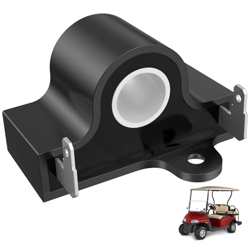
Fits all EZGO TXT, DCS, Medalist and PDS electric golf cart models 1994-up
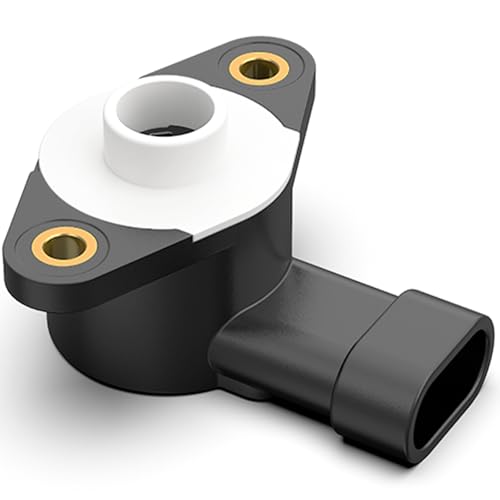
Compatible Models: Golf cart throttle position sensor accelerator is suitable for Yamaha G29, Drive, YDRE 2007-2013 electric golf carts. Not suitable for yamaha G9, G14, G16, G19, G20, G21, G22 golf cart
Step 4: Check the Controller’s Output While Pressing the Pedal
Set your multimeter to DC volts and connect the probes to the output terminals, typically B- and M-. Keep the cart safely supported with drive wheels off the ground, turn the key on, and engage drive mode. With solid probe contact, watch the meter as you press the accelerator slowly. At rest, you should read near 0 volts. As you move the pedal, the voltage should increase smoothly toward the full battery-pack voltage at maximum pedal travel—this indicates proper voltage stability and good pedal calibration. Avoid pressing too quickly; slow, deliberate sweeps reveal dead spots or sudden jumps. Repeat several times to verify consistent output. A gradual, predictable voltage change means the controller’s output stage is functioning correctly. If the voltage stalls or fluctuates erratically, it signals a likely problem, but that requires further diagnosis. Confirming this smooth voltage increase helps rule out a motor fault when voltage behavior is inconsistent. For reliable testing, ensure the battery pack voltage remains stable, as a weak charger can cause false readings. Pay attention to the physical condition of the wheel covers during testing, as loose wheel hardware can introduce false vibrations that mimic controller issues. Choosing a durable seat cover can help maintain your comfort during longer diagnostic sessions.

Large Display Screen: This battery monitor has multiple display functions, including temperature, voltage, and capacity. Large widescreen 4.5 cm(1.7 inch) * 2.5 cm(1 inch), more clear

{A Must Have LED Battery Monitor Indicator } - The battery indicator is used to measure the remaining charge in the golf cart battery, including lithium battery, lead acid battery, lithium iron phosphate battery, 3-15 series lithium ion battery, storage battery, water battery and other different battery types.Freely switching voltage among 12V 24V 36V 48V 60V 72V

Compatible Models: Suitable for Club Car Precedent/Tempo gasoline and electric models manufactured in 2014 and later
5 Signs Your Golf Cart Controller May Be Faulty
If your golf cart controller is starting to fail, you’ll notice several clear signs. One common symptom is jerky or uneven acceleration, along with sudden surges in speed. This indicates the controller’s output is becoming unstable. You might also observe a reduced top speed or the cart entering limp mode, especially when navigating hills. If the cart responds with no movement, stalls unexpectedly, or moves intermittently—simply clicking but not driving—these are strong warning signs. Additionally, look out for excessive heat, a burning smell, buzzing noises, or fault lights on your dash. These are direct indicators of a controller malfunction. Running a proper diagnostic can confirm whether the controller itself is faulty. Ignoring these signs can lead to worsening performance and potentially complete controller failure over time. For that reason, upgrading your motor and controller together can safely increase performance through speed enhancements. For those seeking reliable alternatives, top gas-powered models reviewed for quality and performance can offer a different power source entirely. If you prefer electrical reliability, consider models topped in reviews for lithium golf cart performance.
All Tests Passed? How to Confirm and Replace the Controller
Once you’ve run all diagnostic tests and confirmed that the controller behaves normally—indicating smooth throttle response, correct voltage output, and no erratic behavior—you should verify your results and proceed with replacement if necessary. Begin by confirming electrical values: set your multimeter to DC mode, check the input voltage at the battery pack level (typically 36V or 48V), and ensure the output voltage increases smoothly when pressing the pedal. A faulty controller often fails to regulate power flow properly, which can cause jerky movement or stalling during operation. To avoid these issues, it is wise to review top controller options when selecting a new unit for your specific golf cart model. Inspect supporting components such as wiring, connectors, and terminals for signs of corrosion, loose connections, or damage before swapping parts; this helps prevent future issues. To replace the controller, switch the key to tow mode in your system, disconnect the battery to avoid shorts, label each wire precisely to ensure correct reconnection, and clean all terminals thoroughly. When installing the new unit, torque all connections to the manufacturer’s specifications to guarantee secure contact, and ensure motors are securely held in place on the designated bracket. Ensure the solenoid you select provides consistent voltage handling to match your cart’s battery system for reliable operation. After installation, perform a test drive, focusing on slow throttle application, forward and reverse movement, and smooth acceleration to confirm proper operation. Finally, double-check all connections and wiring before resuming normal use. This thorough approach minimizes the chance of overlooking hidden issues and helps ensure your controller replacement results in a lasting fix.